Driveshafts for Vehicles (Mechanical Devices)
The driveshaft is a high speed, low bearing rotating body, so its dynamic balancing is critical. Usually, the driveshaft is dynamically balanced before it leaves the factory and is adjusted on a balancer. For front-engine rear-wheel-drive cars, it is the shaft that transmits transmission rotation to the main reduction gear, which can be several knots, knuckle to knuckle. It can be connected by universal joints.
Function
The driveshaft is an important component in the transmission that transmits power to the engine along with the gearbox and drive axle. Transmits to the wheels to generate driving power for the vehicle.
Application
Special vehicles transmission shaft is mainly used in tanker trucks, fuel trucks, fuel trucks, sewage trucks, vacuum trucks, fire trucks, high-pressure washing vehicles, road On wrecker, aerial work truck, garbage truck, and other models.
Structure
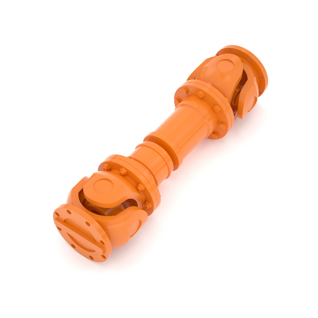
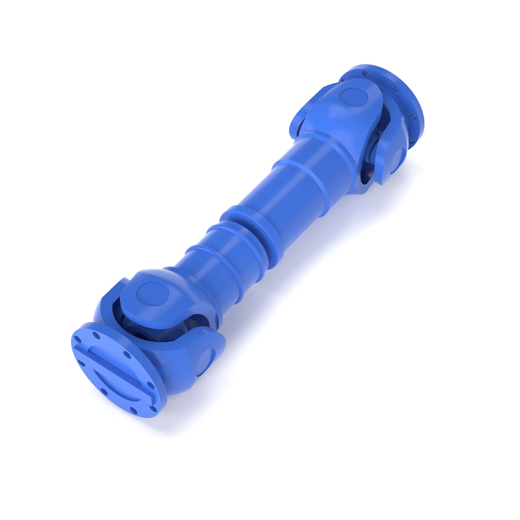
The drive shaft consists of an axle tube, a telescopic sleeve, and a universal joint. The telescopic sleeve automatically adjusts the distance between the transmission and the drive axle. The universal joint ensures the variation of the angle between the output shaft and the input shaft of the drive axle and enables an equidirectional transmission of the two axles.
Universal Joints
The gimbal is a key component in the drive shaft of an automobile. A car is a moving object. In a rear-drive vehicle, the engine, clutch, and transmission are mounted as a single unit on the frame, while the drive axle is connected to the axle via a flexible suspension. The frame is connected and there is a distance between the two that needs to be connected. The uneven surface of the car in operation produces runout.
A general universal joint consists of a cross shaft, a cross-bearing, and a flange fork. The universal joint is a key component of the vehicle's driveshaft. In front-engine rear-wheel-drive vehicles, the gimbal drive shaft is mounted between the transmission output shaft and the input shaft of the drive axle main reducer. For vehicles with front-engine front-wheel drive, the drive shaft is omitted and the universal joint is mounted on the front axle half-shaft, which is responsible for both driving and steering between the wheels. Run-out from uneven road surfaces, load changes or differences in the mounting positions of the two assemblies can cause the output shaft of the transmission to shift in relation to the angle and distance between the input shafts of the main reduction gearbox of the drive axle changes, so a "variable strain" device is used to solve this problem. A problem, hence the universal joint.
In a car with front rear-wheel drive (or all-wheel drive) engine, as the suspension deforms while the car is in motion, the drive shaft primary There is often relative movement between the input shaft of the reducer and the output shaft of the transmission (or transfer case) and, in addition, to effectively avoid certain mechanisms or devices. (cannot achieve straight-line transmission), there must be a device to achieve the normal transmission of power, so the emergence of the gimbal drive. The gimbal drive must have the following characteristics:
a, to ensure that the relative position of the two axes connected within the expected range of change, can be reliable Transmitting power;
b, to ensure that the two axes connected to the uniform operation. The additional load, vibration, and noise caused by the angle of the universal joint should be within the allowable range;
c. The transmission efficiency should be high and the service life should belong. Long, simple structure, easy to manufacture, and maintain.
In the case of automobiles, since the output axis of a cross-axis gimbal is not rotating at the same speed relative to the input axis (with a certain angle). For this purpose, it is necessary to use a double (or multiple) universal joint drives and to arrange the two universal joint forks connected to the driveshaft in the same plane. And make the angles of the two gimbal joints equal. This is very important. The angle of the Cardan joint should be designed to minimize the angle.
Expansion sleeve
The conventionally constructed driveshaft telescopic sleeve has the spline sleeve welded to the flange fork and the spline shaft welded to the driveshaft tube. The new driveshaft changes the traditional construction by welding the spline sleeve to the driveshaft tube as one piece.
The spline shaft and the flange fork are made in one piece. The rectangular tooth spline is replaced by a short tooth spline with a large pressure angle involute, which increases the strength and facilitates the extrusion process to adapt to high torque. Required by the operating conditions. The tooth surfaces of the expansion sleeve and spline shaft are completely coated with a nylon material that not only increases wear resistance and self-lubricating properties, but also provides a high degree of protection against wear. Reduced shock load damage to the driveshaft and improved cushioning capability.
The driveshaft is protected by a tubular seal sleeve outside the flange splined shaft, with two polyurethane rubber seals on the end of the sleeve. The oil seal makes the expansion sleeve form a completely sealed space inside the sleeve so that the expansion spline shaft is not eroded by the external sand and dust, which is not only dustproof but also has the advantage of being dustproof. Anti-rust. Therefore, a one-time application of grease in the splined shaft and sleeve during assembly can completely satisfy the requirements of use, without the need for grease nipple lubrication. Reduced maintenance content.
Bushing
It is designed to reduce friction and wear during shaft movement, and its basic purpose is the same as that of bearings, and it is relatively inexpensive. They have higher frictional resistance, so they are only used in some parts. Most bushings are made of copper, but plastic bushings are also available. The sleeve is placed between the shaft and the support and is so close to the support that only the shaft can rotate on the sleeve. When assembling the shaft and the sleeve, a lubricant is added between the two to reduce the friction caused by their rotation.
Types
By flexibility
Driveshafts can be classified differently depending on their important component, the gimbal. If according to the universal joint in the direction of torsion whether there is obvious elasticity can be divided into rigid universal joint driveshaft and flexible universal joint drive shaft.
- rigid universal joint: transmission of power by the hinged coupling of parts.
- Flexible universal joint: rely on the elastic parts to transfer power, and has a cushioning damping effect.
According to the angular velocity
Rigid universal joints can be divided into unequal speed universal joints (such as cross-axis universal joints), quasi-equal speed universal joints (such as twin universal joints, three-pin universal joints), and rigid universal joints. Axial Universal Joints) and Constant Velocity Universal Joints (e.g., Ball-Cage Universal Joints, Ball-Fork Universal Joints). Constant and unequal velocity, in terms of whether the angular rate of rotation of the slave shaft is equal when the two are rotating with the active shaft, and of course The average speed of the master and slave shafts are equal.
- The constant velocity of Cardan joints.
A gimbal where the angular velocity of the main and driven axes is equal even when the angle between the two axes changes is called an isotropic gimbal or isotropic gimbal. They are used in wheel transmissions for steering drive axles, disconnect drive axles, etc., and are mainly used for power transfer in cars.
- unequal speed universal joints.
A gimbal in which the angular velocity of the master and slave axes are not equal when the angle between the two axes changes is called an unequal gimbal also called across. Shaft Type Universal Joints. Cross-shaft rigid universal joint drive shaft in the automotive driveline is the most widely used and has the longest history. When the car for the rear-wheel-drive, often cross-shaft universal joint drive shaft, part of the high-grade cars, there is also equal speedball head; when the car is rear-wheel drive. Sedan for the front-wheel-drive is often used isochronous universal joint - the isochronous universal joint is also a kind of drive shaft, but the name is different. Usually refers to a drive shaft is the cross-shaft rigid universal joint drive shaft. The cross-shaft rigid universal joint is mainly used to transmit the angle change, generally by the flange fork, cross-shaft with needle roller bearing assembly, universal joint fork. Or sliding fork, intermediate connection fork or spline shaft fork, needle bearing axial fixings, and other components. The flanged fork is a flanged fork-shaped part, generally using medium carbon steel or medium carbon alloy steel forgings, but also using ductile cast iron forgings. Sand castings and precision castings of medium carbon steel or medium carbon quality alloy steel. Flange forks generally come with a flat flange, but also with an end trapezoidal tooth flange. Cross shaft with needle bearing assemblies generally consists of four needle bearings, a cross shaft, and a grease nipple. Needle roller bearings generally consist of a number of needles, a bearing bowl, and a multi-bladed rubber oil seal (some with a skeleton). In some needle roller bearings, there is also a circular gasket with oil groove, nylon, copper, or other materials, the main Used to reduce the universal joint axial clearance, improve the dynamic balance quality of the drive shaft. A universal joint fork is a fork-shaped part, generally using medium-carbon steel or medium-carbon alloy steel forging parts, but also the use of medium-carbon steel precision casting parts. The axial fixings of needle roller bearings are generally elastic retaining rings (internal and external snap type) for the holes (or shafts) or bearing clamps, lock plates, bolts, etc.
Dynamics
When we trade in a car, we must conduct a road test, however, it is important to consider the vehicle's Dynamics, so what is a car's dynamics?
The dynamics of a car are the process of driving in a straight line on a good road surface, which can be determined by longitudinal external forces accordingly The driving performance of a road is the ability to achieve the average driving speed required. As we can see from this definition, the road must be a good surface, either level or sloping. The movement can take the course of a straight line, and for external factors, the longitudinal forces can be used to determine the basis of the movement, making Its ability to achieve a certain level of capability. For sporting ability, there are three main indicators, such as the maximum speed of the car, the acceleration time, and the maximum climbing grade. For a vehicle that is driven on a good level surface, if it is able to reach its maximum driving speed, we call it maximum speed. For the acceleration time, which is usually the time it takes to accelerate from a standing start and the time it takes to overtake and accelerate, this time indicates the car's Acceleration ability. "t" indicates the time for starting at the same place, usually in first or second gear, and gradually shift gears. The time it takes for the car to reach a certain predetermined distance. It is the time it takes to start from the spot. The acceleration time for overtaking can also be expressed in "t", and the largest cars in the second class are about 30 or 4. The full acceleration is indicated by the time spent on some highways.
Use and Maintenance
In order to ensure the normal operation of the drive shaft, extend its service life, in use should pay attention to 1. strictly forbid the car with high-speed gear to start. 2. It is forbidden to lift the clutch pedal. 3. It is forbidden to overload and over-speed the car. 4. The driveshaft should be checked frequently. 5. Always check the tightness of the drive shaft hanger, whether the bearing rubber is damaged, whether the connection parts of the drive shaft is loose, whether the drive shaft is deformed. 6. in order to ensure the dynamic balance of the drive shaft, constant attention should be paid to the balance weld lug is not desoldered. The new drive shaft assembly is supplied as a kit. in a plane. When disassembling the drive shaft for repair, the assembly markings should be printed on the expansion sleeve and the flange shaft in order to maintain the original assembly relationship when reassembling. 7. should always be filled with grease for the universal joint cross-bearing, the summer should be filled with lithium 3 grease, winter lithium 2 greases, and Grease.
Troubleshooting
Wear and tear issues
Damage, wear, deformation and loss of dynamic balance of the drive shaft components can cause abnormal sounds and vibrations in the vehicle, which can be severe. This can lead to damage to the relevant parts when the car is running. When the vehicle is in motion, a "guttural" sound is made when starting or accelerating, and there is a noticeable feeling of looseness of the mechanism if it is not "guttural". Drive axle drive gear loosening is obviously the drive shaft mechanism loosening. Loose parts are nothing more than a universal joint cross-bearing or steel bowl and flange fork, expansion sleeve of the spline shaft and spline sleeve. In general, the cross shaft diameter and bearing absenteeism should not exceed 0.13mm, expansion spline shaft and spline sleeve mesh clearance should not be greater than If the vehicle exceeds the service limit, it should be repaired or replaced.
If the chassis buzzes while the car is running, and the higher the speed, the louder the sound will be. This is usually due to the wear and tear of the universal joint cross-axle and bearing, wear of the intermediate bearing of the driveshaft, damage to the intermediate rubber bearing, or loosening of the hanger. Or due to the hanger fixed position is not right.
1)Traditional method domestic driveshaft wear generally adopts the methods of re-welding, bushings, pitting and so on, but when the shaft material is When 45-gauge steel (quenched and tempered) is treated with overlays only, internal stresses in the weld can occur, which can lead to stresses in heavy loads or high speeds. In this case, cracking or even fracture may occur at the shoulder, which is difficult to handle if stress relief annealing is used, and processing is not easy. Long cycle times and high overhaul costs; cast iron welding is also not ideal when the shaft is made of HT200. Some companies with higher repair techniques use brush plating, laser welding, micro-arc welding, and even cold welding, which often require higher requirements and high costs.
(2) the latest repair methods for the above repair technology, in Europe, America, Japan, and Korea enterprises have been less common, developed countries generally use polymer Composites and nanotechnology, polymer technology can be operated on-site to effectively improve maintenance efficiency and reduce maintenance costs and Repair strength, the most widely used of which is the Megawatt technology system. Compared to conventional technologies, polymer composites have the strength and hardness required by metals, but also have a degenerative property that metals do not have. (variable relationship), and the "mold repair", "part correspondence", and "machining" processes ensure that the maximum number of parts can be repaired. The dimensional fit of repair and mating parts; at the same time, using the composite material itself has a combination of pressure resistance, flexural resistance, ductility, etc. The advantage is that it can effectively absorb the impact of external forces, greatly defuse and offset the radial impact of the bearings on the shaft, and avoid the gap. Possibilities and the secondary wear of the equipment due to increased clearance are avoided.
Balancing problems
Diagnosis of symptoms: 6×4 car in heavy load, especially in the driving bumps occasionally make knocking sound, should pay attention to check the rear axle balance axle If there is any interference with the driveshaft due to dislocation. If the noise increases with increasing speed and shuddering when the car is running, this is generally due to the drive shaft being out of balance. This vibration is most noticeable in the cab. The unbalance of the drive shaft should be measured at less than 100 g. cm. Damage. The most common are clutch housing cracks and fatigue damage to the intermediate rubber bearings.
Solution.
Tighten the front wheels with wooden pads and jack up the middle and rear drive axles on one side of the car; start the engine, put it in high gear and watch. Driveshaft oscillation condition. If the oscillation increases significantly when the rotation speed decreases, it means that the drive shaft is bent or the flange is crooked.
Driveshaft bending is shaft tube bending, mostly due to overloading caused by the car. Coal vehicles due to overload, overhanging, drive shaft bending, broken failure occurs more. Such as some cars plus trailers pulling more than 60 tons of coal, the drive shaft due to overload, overhanging damage seriously. Although the reinforcement of the drive shaft intermediate support, and strengthens the strength of the flange fork, there is still broken damage failure.
After replacing the driveshaft parts and straightening, the balance check should be carried out and the unevenness measurement should meet the standard requirements. The technical condition of the gimbal fork and the drive shaft hanger should also be checked in detail, such as the damage of the cross shaft and rollers due to installation failure. Looseness and vibration can also throw the driveshaft out of balance.


